Gear Parameter Analysis
Before production, we check the module, number and profile of teeth, mounting dimensions, material, and accuracy requirements for the gear mesh.
We manufacture gears based on drawings, 3D models, or samples: spur gears, helical gears, bevel gears, gear wheels, and gear shafts. For complete part manufacturing, we also provide turning services and metal milling . We perform gear cutting for both single parts and production batches.
From a drawing
3D model or sample
Different types
of gears and gear wheels
From 1 part
to series production
Steel and alloys
to suit part requirements
Gear cutting
for external and internal teeth
Quality control
of geometry and dimensions
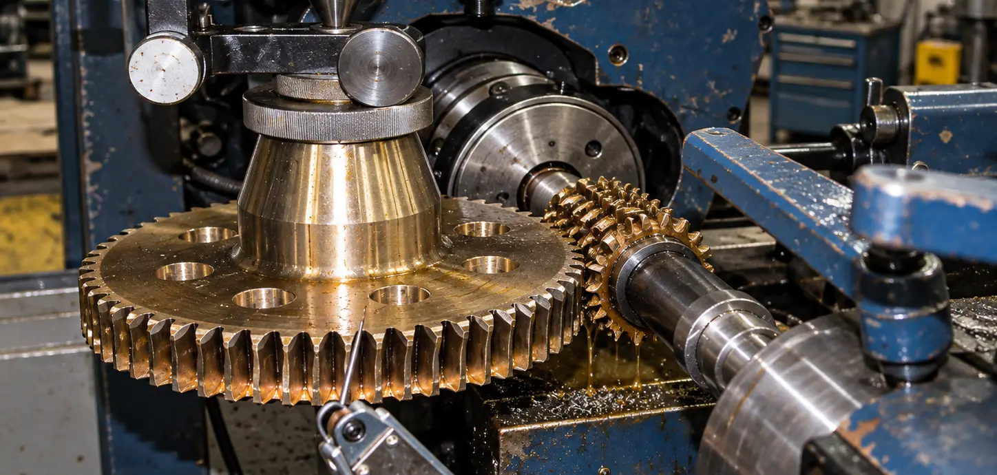
Gear production begins with blank preparation and precision machining of mounting surfaces, followed by gear cutting with consideration of module, number of teeth, helix angle, and the required meshing geometry. Depending on the part design, external or internal gear cutting is used, while machining parameters are selected according to the material and accuracy requirements.
We manufacture spur, helical, and bevel gears, gear wheels, gear shafts, and other gear transmission components for gearboxes, drives, machine tools, and industrial mechanisms. We work with both single parts and production batches, controlling tooth profile, mounting dimensions, concentricity, and part geometry to ensure proper meshing and stable operation of the mechanism.
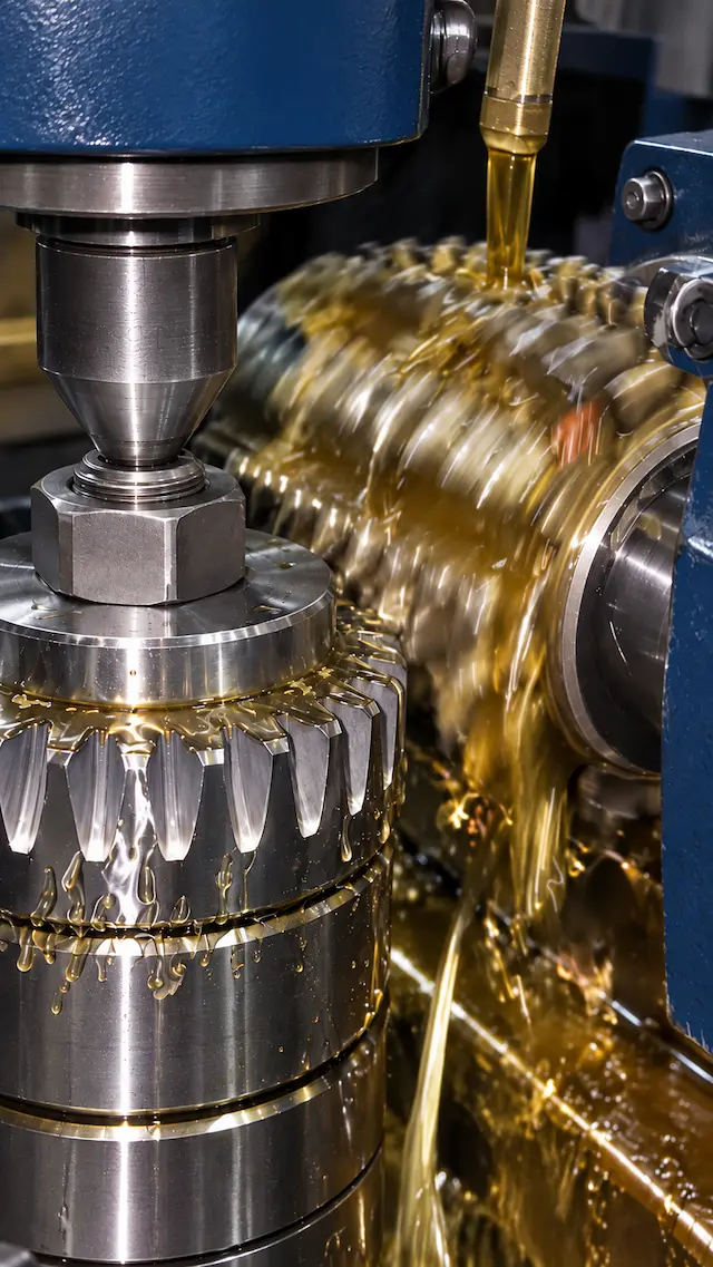
Steel is used for most industrial gears due to its combination of strength, rigidity, and wear resistance. The grade is selected according to the load, operating speed of the gear transmission, required tooth hardness, and subsequent heat treatment.
Typical materials:
Low-carbon alloy steels followed by carburizing and hardening are used for heavily loaded gear transmissions. After this treatment, the tooth surface becomes hard and wear-resistant, while the core retains toughness and better withstands impact loads.
Typical grades:
Induction hardening is used when the hardness and wear resistance of the working tooth surface need to be increased without through-hardening the entire part. This method is used for gears, gear wheels, and gear shafts operating under cyclic loads.
Typical materials:
Stainless steels are used for gear components operating in humid, chemically aggressive, or other corrosive environments. The specific grade is selected based on the required strength, heat treatment method, and operating conditions of the transmission.
Possible materials:
Bronze is primarily used in worm gear drives where wear resistance, good anti-friction properties, and stable operation with a steel worm are important. The wheel material is selected together with the material and hardness of the worm.
Typical materials:
Polymer gears are used in mechanisms with low to moderate loads where low weight, low noise, corrosion resistance, or operation with minimal lubrication is important. The material is selected according to temperature, speed, and load.
Typical materials:
The module determines the main tooth dimensions and is one of the key parameters for gear pair compatibility. During manufacturing, the module, number of teeth, pitch diameter, face width, and other parameters defined by the transmission design are taken into account.
The gear cutting technology depends on the type of meshing. For spur and helical gears, the direction and helix angle are taken into account, while for internal gearing, the gear rim geometry, tool accessibility, and part design are considered.
The pressure angle affects the meshing geometry, tooth loading, and compatibility of the mating components. A 20° pressure angle is commonly used for many modern involute gear systems, but the required value is taken from the technical documentation for the specific mechanism.
The required accuracy is determined by the application, rotational speed, load, and requirements for noise and smooth operation. For cylindrical involute gears, accuracy requirements may be specified in accordance with ISO 1328-1 or another standard stated in the technical documentation.
During inspection of the gear teeth, deviations in pitch, profile, and tooth lead are evaluated. These parameters directly affect load distribution, tooth contact, and smooth operation of the mechanism.
For a gear, not only the tooth shape matters but also the position of the gear teeth relative to the mounting bore or reference surfaces. Controlling concentricity and radial runout helps prevent uneven meshing, vibration, and local tooth overload.
The mounting section is manufactured according to the method used to secure the gear on the shaft. This may include a cylindrical or tapered bore, keyway, spline connection, thread, or another design. Fit tolerances are specified separately from the gear tooth parameters.
Carburizing, through hardening, induction hardening, nitriding, and other heat treatment methods may be used to increase transmission service life. The treatment process is selected according to the steel grade, load, and required surface hardness. For precision gears, additional finishing of the teeth may be required after heat treatment.
For transmissions with increased requirements for accuracy, noise, and smooth operation, gear grinding or another finishing process may be applied after gear cutting and heat treatment. The need for this stage depends on the required accuracy grade and operating conditions.
Backlash is specified for the gear pair as a whole, taking into account the gears, centre distance, fits, and operating temperature of the mechanism. For critical transmissions, these parameters must be considered together to ensure free rotation without jamming or excessive play.
Before production, we check the module, number and profile of teeth, mounting dimensions, material, and accuracy requirements for the gear mesh.
We calculate the cost, production lead time, and required manufacturing operations before the order is released for production.
We inspect tooth profile and pitch, mounting surfaces, concentricity, runout, and other parameters that affect correct gear operation.
We organize the manufacturing, inspection, and delivery of gears, gear wheels, and gear shafts across Ukraine.
Examples of manufactured gears, gear wheels, gear shafts, and other gear transmission components for industrial machinery and equipment.
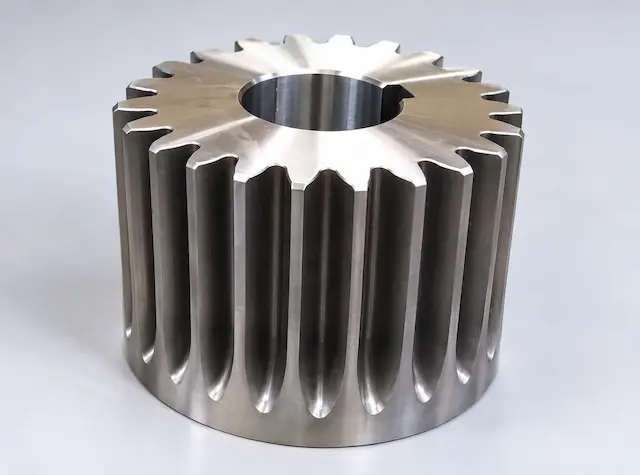
Material: Steel 45. Gear cutting and machining of the mounting bore. Batch — 8 pcs.
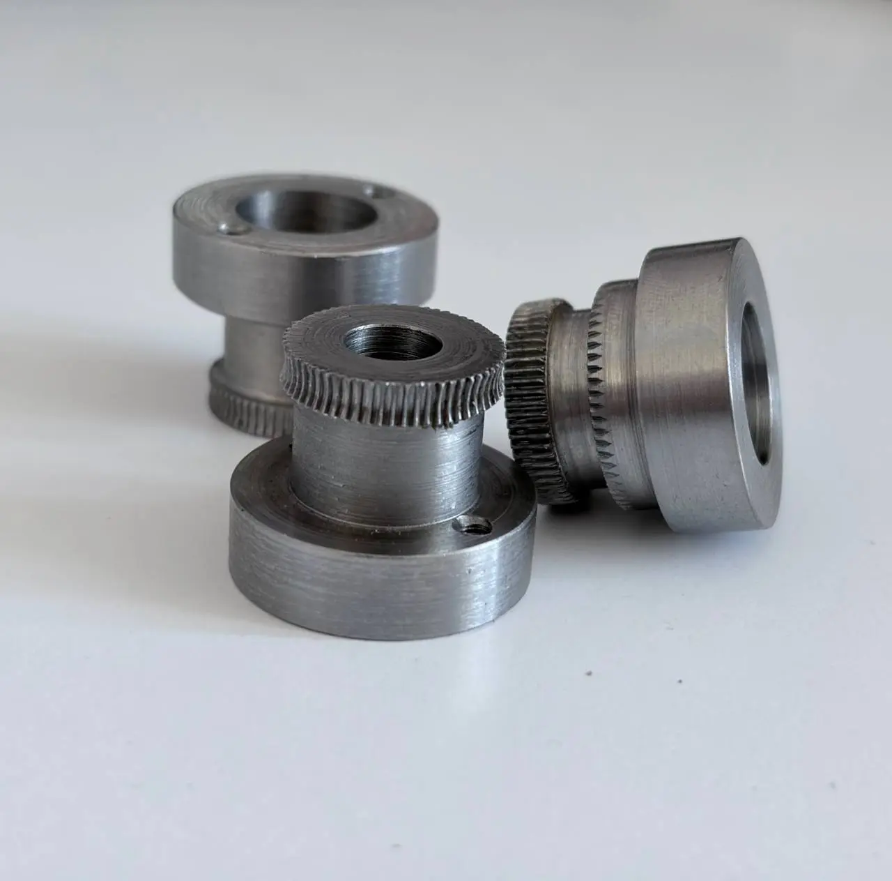
Material: 40Х steel. CNC turning and gear cutting. Batch — 20 pcs.
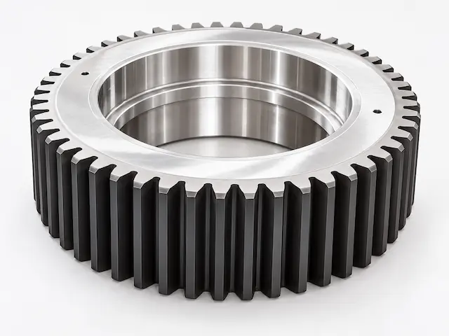
Material: 40Х steel. External gear cutting, machining of the internal mounting bore and end faces. Batch — 60 pcs.
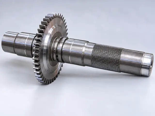
Material: 40Х steel. Turning, gear cutting, and spline machining. Batch — 4 pcs.
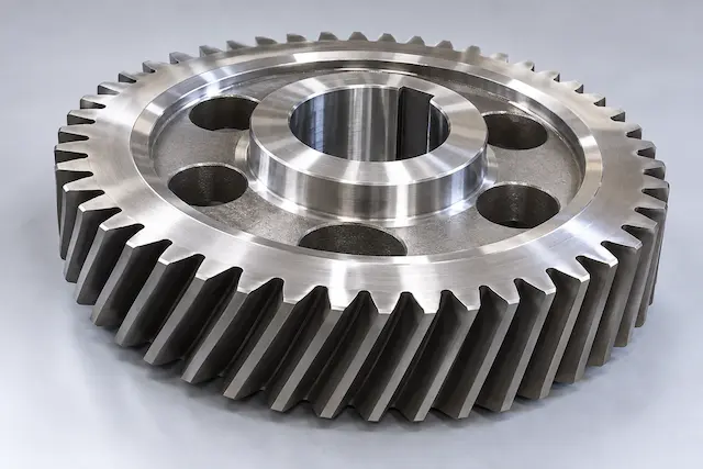
Material: 40Х steel. Helical gear cutting, machining of the mounting bore and keyway. Batch — 1 pc.
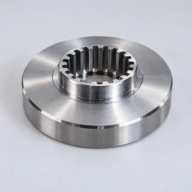
Material: 40Х steel. Body machining and internal spline cutting. Batch — 168 pcs.
Lead times depend on the part design, material, module, number of teeth, required accuracy, and batch size. Additional time may be required for heat treatment, grinding, or other finishing operations.
The cost depends on the part dimensions, material, type of gear mesh, module, number of teeth, machining complexity, accuracy requirements, and quantity of parts in the batch.
We manufacture spur, helical, and bevel gears, gear wheels, gear shafts, and other gear transmission components. The manufacturing process is selected according to the design and operating parameters of the specific part.
Yes, an existing sample can be used to determine the geometry and main parameters of the part. For critical mechanisms, the material, fits, hardness, and operating conditions of the transmission are additionally specified.
We can manufacture such parts depending on the internal diameter, module, gear rim width, and part design. The gear cutting method is determined after evaluating the technical parameters.
Yes, we work with single parts, small batches, and series production. For series production, particular attention is paid to repeatable geometry and stable part parameters.
Heat treatment is not required for every part. Its necessity depends on the material, load, operating speed, and wear resistance requirements. Depending on the application, carburizing, hardening, nitriding, or other strengthening methods may be used.
Upload a drawing or 3D model and we will prepare an accurate quote. Or simply describe your requirements, and we will help you work out the details.


